
While 3D printing is known for design freedom, this manufacturing method still has its own hurdles when it comes to design. Appropriately named additive manufacturing, each layer builds on the previous one and needs physical substance to build on. Additional design guidelines are result of the printer technology, and the method in which a part is printed.
3D Printing vs. Traditional Manufacturing Methods
Design Benefits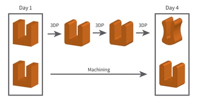
There are less limitations when designing a part for 3D printing. Wall thicknesses do not have to be consistent throughout the part, and they can also be much thinner than that of a part that is injection molded or machined. In addition to this, draft angles do not have to be considered like they do when designing for injection molding.
Features like hollow cavities, pockets, and undercuts are much easier to achieve with 3D printing than they are when injection molding or CNC machining. 3D printing does not require considerations of sprues, like that of injection molding, or the use of multiple tools, like CNC machining. Organic shapes are much more achievable for printed parts than for machined parts as a result of printing technology and the design freedom that comes along with it.
Cost Benefits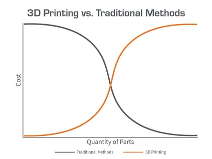
An additional benefit of 3D printing in comparison to other methods of manufacturing is the low cost of an individual part. For most traditional methods of manufacturing, it is not cost effective to build parts at low quantities. However, with additive manufacturing, thousands of end-use parts can be printed at a low cost as opposed to the high cost of a mold or machining labor hours.
There will always be a point in which using a different method of manufacturing will be the cheaper method once a large enough quantity is needed. However, design changes are often expensive and have long lead times for parts manufactured with traditional methods. If a high quantity is needed, the design of a part can be tested and changed in a matter of hours, rather than days or even weeks required to implement design changes with injection molding or CNC machining. This allows for the design of a part to be perfected at a low cost before going through with implementing the final design, rather than having expensive design changes.
B9Creations Design Guide
When designing parts for 3D printing, there are a few design elements to keep in mind in order to ensure your print turns out as desired.
The design and supporting of a model varies based on the resin used.
Overhang Angle
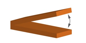
Overhang angle is the angle between the build table and the part. The closer overhanging features are to being parallel with the build table, the less self-supporting they will be.
Minimum Self-Supporting Angle: 45⁰ - 50⁰
Angles less than 45⁰ require supports
Length of overhanging features is important – longer overhanging surfaces need more supporting
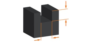
Vertical Wall Thickness
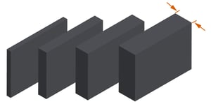
Vertical walls are walls that are perpendicular to the build table. The thinner they are, the less structural integrity they have.
Minimum Thickness: 0.1 - 0.4 mm
Thin walls connected on more than one side are more likely to print successfully
Horizontal Wall Thickness
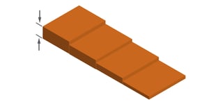
Horizontal walls are walls that are parallel to the build table. The thinner they are, the less structural integrity they have.
Minimum Thickness: 0.1 - 0.3 mm
Walls connected on more than one side are more likely to print successfully
Horizontal Bridge Distance
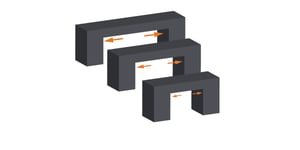
A horizontal bridge is a bridge that is parallel to the build table and supported at both ends.
Maximum Distance Without Supports: 1 - 8 mm
Bottom layers of bridge prone to warping first
Horizontal Hole Diameters
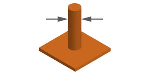
A pin is a rod extruding from a surface, at an angle between 0⁰ and 90⁰.
The thinner the pin, the less structural integrity it has.
Minimum Diameter: 0.1 - 0.3 mm
Same considerations as that of an overhanging feature if applicable
Same considerations as that of a horizontal bridge if applicable
Hollow Cylinder Wall Thickness
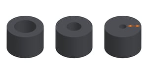
Hollow cylinders are cylinders that are not filled in. They typically print best if they are perpendicular to the build table to avoid having to place supports within the cylinder.
Minimum Thickness: 0.1 - 0.3 mm
If cylinder is too small, the hole on the inside may fail and the feature will print as a solid cylinder.
Ratio of Material to Print Size
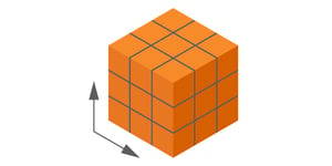
This ratio describes the amount of material necessary in comparison to the size or build volume of a print.
A print that is large is going to lack structural integrity if it is made up of only very thin walls that do not connect frequently
In order to have a stable print, the part needs to be thick enough with sufficient connected feature points so that it can support itself throughout the print process
Hollow Cavities and Pockets
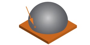
Hollow cavities and pockets tend to lead to suction forces which can ultimately lead to failure of the print.
Part orientation is important – orient parts so that open pockets are perpendicular to build table
Hollow cavities and pockets whose orientation cannot be fixed require escape holes, or holes that relieve suction forces
Embossed Details
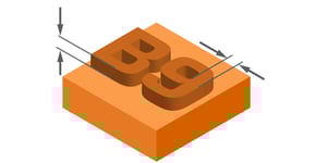
Embossed details are details that are raised up from a surface. Typical details that are embossed include words, logos, patterns, etc.
Minimum Width: 0.1 mm
Height is dependent on the width – the wider the feature, the taller it can be
Engraved Details
Engraved details are details that are etched or inscribed into a surface. Typical details that are engraved include words, logos, patterns, etc.
Minimum Width: 0.1 - 0.2 mm
Depth is not dependent on width – as long as the width of the engraved detail is greater than the minimum, the depth can be as deep as needed
Model Orientation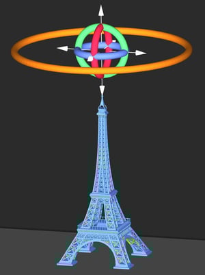
The orientation of a part on the build table is a critical factor to success. The three things to consider when orienting a part are dimensional accuracy, where surface finish is important for the end use, and minimizing the number of supports to be added.
- Dimensional accuracy needs to be considered given that the first layers of the build are often over-cured in order to ensure adhesion to the build table, which can affect the dimensions of those first few layers.
- Surface finish is important because there is slight damage to the finish of the areas in which supports are to be removed, therefore the most important surfaces should be oriented away from the build table to avoid the need for supports.
- Minimizing the number of supports minimizes the areas in which the surface finish will be damaged from support removal.
Features like hollow cavities and pockets allow for suction forces during the print process. Adjusting the orientation of the part so that it is positioned in such a way that the opening to the cavity is perpendicular to the build table fixes this problem, as it does not allow for resin to be trapped between the part and the vat. However, doing so is not always feasible. To combat this, adding escape holes is recommended in order to relieve the suction forces, allowing material to escape and air to be let in.
*All information will vary slightly, depending on the resin and resolution of your print.


