1. Importing Files
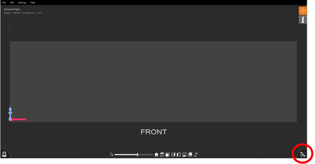
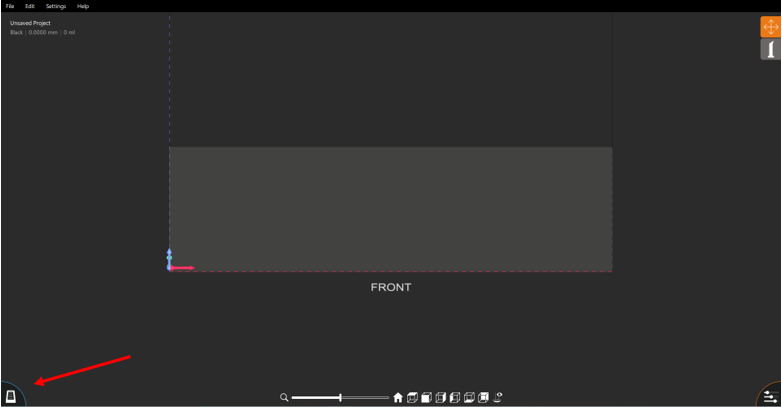
To import the .stl file into Create, open the control tab by pressing the button in the bottom right-hand corner of the viewing window. This opens the control tab, which is essential to operating Create.
The first step of importing a file is to select the type of printer and resin. This can be found inside the control panel in the Info section. Just below the material selection use the ‘add’ button to import the .stl file from the file explorer of the computer. The .stl files contain internal dimensions and using the drop down menu next to the add button, Create will automatically apply the selected units to the internal dimensions of the .stl file.
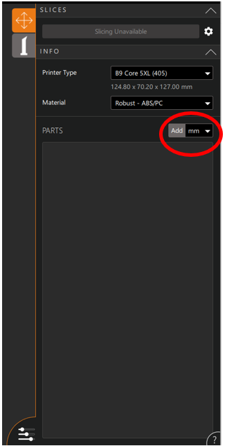
Multiple files can be uploaded into Create. The limiting factor to this feature is the size of the build table.
2. Placing Files
The orientation of the file compared to the build table can significantly affect the need to support the file. Supporting a file is very part specific and too complex for the scope of this article, but a general supporting guide can be found here.
Editing the location and orientation of the part in Create can be performed either manually using the sphere or numerically in the Transform section of the Control tab.
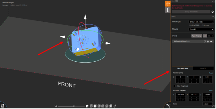
If the manipulation sphere and the Transformation section are invisible, left click on the part.
If necessary, the entire part can be upscaled or downscaled compared to the size of the original .stl file. The Scale can be found in the bottom-right corner of the Translation tab.

3. Supporting Files
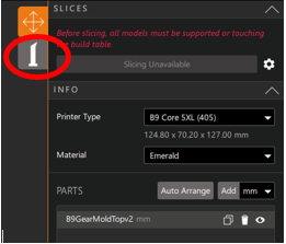
After the part has been positioned in Create, the next step in the pre print process is supporting the part. To begin supporting the file, click on the Supports Tab directly below the orange placement tab in the top right corner of the viewing window. As previously mentioned, the supporting process can vary greatly in its complexity, so instead of explaining how to support pieces this article will merely cover the support tools that exist in Create.
a. To aid in the supporting process Create features a suggested support tool. Any component of the part that may need a support is highlighted in yellow.

Note: This feature can be adjusted during component placement in the Configuration Tab, next to the Transformation Tab
b. Supports can only be placed on the highlighted portions of the part. This is accomplished by left clicking on the part. The characteristics of the supports can be fine tuned by clicking on the support. The control window will display the current dimensions of the support and allow them to be altered.

c. Manually placed supports can also be duplicated along axial planes using the support mirroring feature found at the top of the support tab in the control tab.
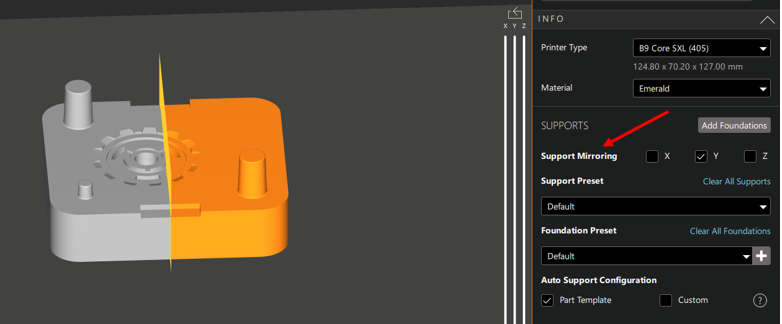
As shown by the figure above, the part is split along an axis (in this case the Y axis) and any supports added to the gray portion of the component will be copied as closely as possible on the orange portion of the part.
d. In versions of B9Create released after 2021 there exists an option to auto support the part. This feature uses an algorithm to predict where supports are needed. This is not a perfect system and may miss some areas where supports are necessary or place frivolous supports that are unnecessary. When using this feature, verify that the auto support function has produced a successful support structure before finalizing the part. In the same drop down menu as the auto support feature, the entire part and all of its supports can be duplicated as many times as will fit on the build table.

To reach this menu right click on the part while in the supports tab
4. Slicing
Once the supports have been placed the last pre-printing step is to slice the part. The slicing section can be found at the top of the Control panel

However, before slicing begins it is important to chose the correct slicer. Printers with Firmware 96 and above can begin slicing using the ‘Start Slicing’ button, but printers with a previous firmware version must use the legacy slicer found by left clicking on the COG. More information about the two different versions of the slicer can be found here.
5. Transferring Files
Now that the .stl file has been supported and sliced in the Create software it must be sent to the B9Creations printer. This can be done one of 2 ways. A USB drive can be used to physically transfer your completed CPJx file from your computer to the printer. Additionally, a CPJx file can be sent directly from the Create software to your printer using the printer manager at the bottom left hand corner of the viewing window.
The B9Creations printer will be added automatically through a shared Wi-Fi connection or can be added manually by inputting the printer I.P. address. The printer I.P. can be found at the bottom left hand corner of the printer home screen.