Orientation, Support and Design Guidelines
Print Created by: Joel HrachovecOrientation, Support and Design Guidelines
TABLE OF CONTENTS
Jewelry
Creative CADWorks Guide to Jewelry Supports
Producing precise 3d models
1. Use the Create Print Editor software to investigate missing design features and errors.
Design mesh must be manifold (watertight). Design files must contain only solid triangle meshes, and files cannot include normals that are pointing the wrong direction.
Hole in the CAD design
2. Add STL files to the Build Table
- Designs must fit inside the specified build area.
- Print areas near the build table surface result in the least detail.
- Models need a strong attachment to the build table.
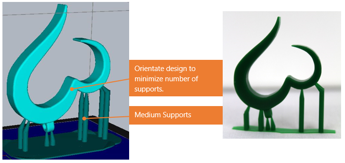
3. Orientate the design for optimal print results and helps minimize the number of supports.
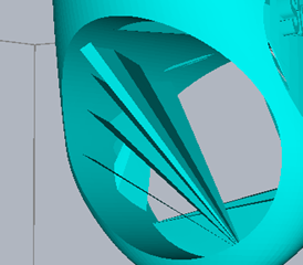
Build Table located at top in pictures
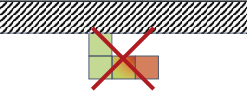 |
Islands (overhangs) areas indicated in red will not print. |
 |
Left – two supports required to print the design. Right – the design is self-supporting. The design builds layer upon prior layer. Orientation affect the quality of the finished print. |
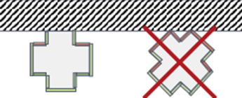 |
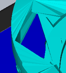
Areas identified in red require supports to print. The example on the right is a poor orientation for this design because only two small points attach the model to the build table which will result in the model separating when the build encounters a larger cross-sectional area. |
4. How many supports are needed and where?
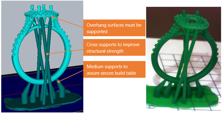
- Overhangs are areas in a part/model that is not supported by a previous layer during the build process and therefore must be supported.
- Converging circle contour lines indicate minimum points on a design.
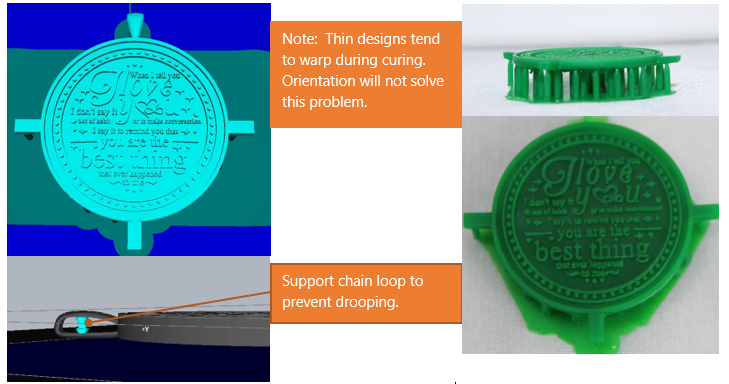
- Support spacing must be less than 1 mm on horizontal surfaces to prevent drooping.
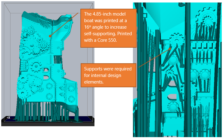
- Use X-Ray Vision to see the interior of the model. This is helpful in placing supports within structures.
- Place supports in areas which are easy to remove and do not affect the design details.
- Ensure supports do not touch your model.
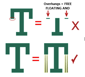
- Cross long supports to improve support strength (see example below).
5. Evaluate print result accuracy to the design. Add additional supports to areas which droop and/or adjust the orientation to increases the area of the design which will self-support.
Auto Supports
The Auto Support tool uses a mathematic algorithm to generate supports. Therefore, the tool may add supports which are not necessary and can miss areas which need supported. Review the results and making the necessary changes.
Jewelry
Creative CADWorks Guide to Jewelry Supports
Supports are the key for the success of majority of the jewelry items we print. Approx. 95% of failed prints are related to lack of supports or inappropriate use of supports.
The user must assure the model is well attached to the Build Table when determining whether to use supports and where to place those supports.
*The use of supports is not universal. It is dependent on:
-
the type of printer the part will be printed on
-
the mass and geometry of the part
-
the material the part is being printed with
There are two types of supports that CCW has identified:
- Load Bearing Supports are the primary supports that will hold a part or additional part(s) or features in place during the build process. Load Bearing Supports are the most crucial of supports. It is considered the foundation building block for a successful build.
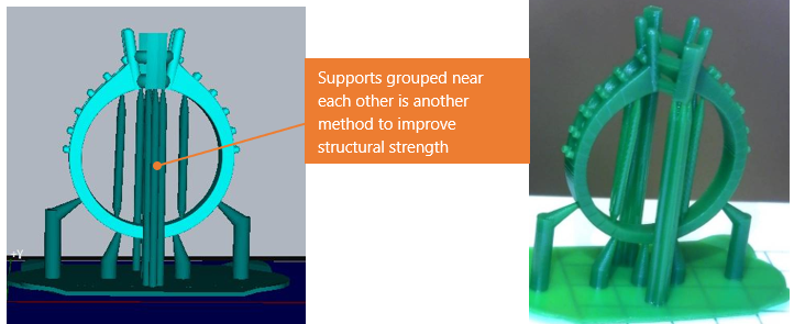
- Structural Supports are not as crucial as Load Bearing Supports. These supports are used to stabilize a model part/feature from shifting during the build process.
A part's Length to Width ratio should be taken in account when determining:
a. whether to use structural support(s)
b. the thickness of structural support(s)
c. the frequency of structural support(s)
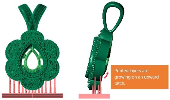
The recommended use for structural supports would take in account for the angle the part/feature is building on. If a given part/feature layer spans greater than 1.5mm horizontally, the use of frequent structural supports would be required (approx. every 1mm to 1.5mm intervals) in order to avoid a downward droop or sag, If the given part/feature is being built on an upward pitch/angle, the spacing interval can be greater (or eliminated) as each layer is being self supported as it extends outwards incrementally.
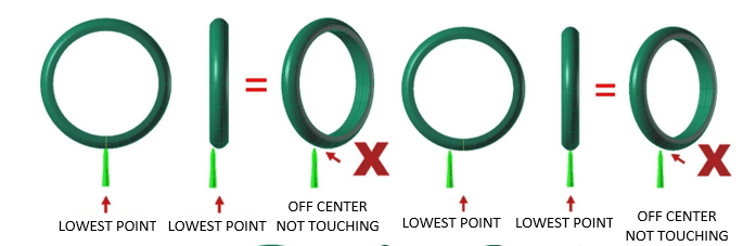
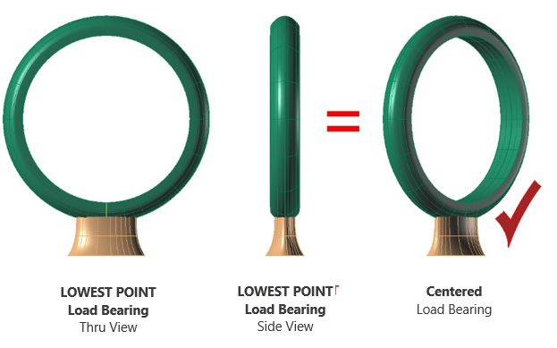
| Load Bearing Supports must intersect the lowest point of the model/part first. The lowest point of the model/part will be the first layer of the part to be printed. The lowest point of the model/part is established by viewing both X and Y axis (or Through Finger and Side View). |
 |
 |
|
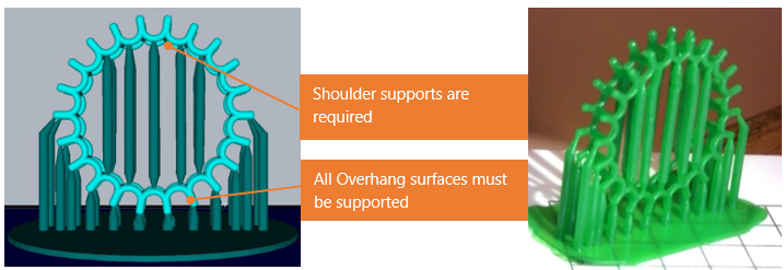
Additionally, load bearing supports must be added to areas to support "Overhangs". Overhangs are areas in a model/part that is not supported by a previous layer during the build process.
|
| Load Bearing Supports can be a single support or multiple supports. This will be determined by the part geometry and mass the support(s) it must bear. |
|
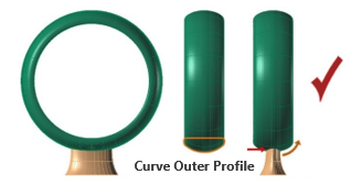
The width of the Load Bearing Support is dependent on the profile of what it will intersect with.
|
|
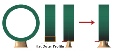
Insufficient bearing support width at the contact point as the outer ring profile is flat and may result in droop due to gravity and lack of support.
|
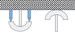
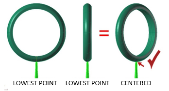
| CCW recommends using a single flared tapered cone support for ring/bands. The cone support extends from approx. 5 O'clock to 7 O’clock and flares out wide where it attaches to the build plate. A Single support can be sufficient for most standard rings/bands. |
|
The width of the cone support connecting to the ring will be determined by the profile of the ring/band. |
|
If the outer profile of the ring/band is domed, the connecting tip of the cone can be smaller because of a reduced surface area and surface tension that would be created during the lift sequence. Conversely, if the outer profile of the ring/band is flat, an increased surface area would exist and would require a larger connection point between the cone support and the ring/band to reduce the surface tension during the lift sequence and to support a larger surface area. The width of the Load Bearing Support is dependent on the profile geometry of what I will intersect with. 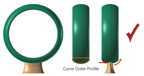
Sufficient bearing support width: The contact point to the ring/band is curved which will be built incrementally layer by layer. 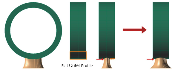
Insufficient bearing support width: The contact point to the outer ring/band profile is flat and may result in a droop due to gravity and lack of support. |
|
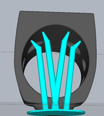
Internal supports for rings/bands. The use of internal supports for rings/bands is dependent on the: a. inner profile b. the width c. thickness A single internal support can be implemented from 6 O’clock to 12 O’clock or a "Branch Supports" from 6 O’clock and midway up branching (fanning out) from 10 O’clock to 2 O’clock.
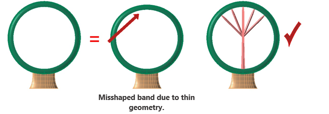
*Note the number of supports in any given axis will be determined by the inner profile of the ring/band and the width and thickness of the ring/band. |
|
Eternity Bands require special attention. To minimize support failures, we implement and outer arc support to reduce the length of the pipe supports required to support down facing prongs. Additionally, its best practice to have the prong situated at 6 O’clock as less supports or even no supports will be required for the under gallery. 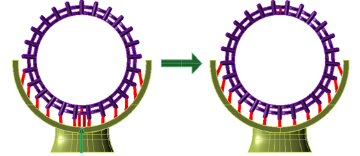
Not ideal because supports are required for the under gallery. |
| Ring |
|
Design Credit: Red Door Distributions |
|
Design Credit: Red Door Distributions |
|
Design Credit: Red Door Distributions |
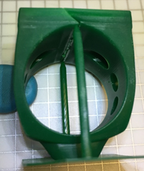
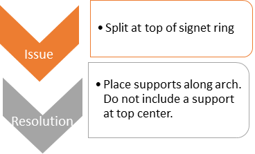
Signet Rings
|
Pendants |
| Ideally, pendants or earrings with flat backs should be orientated flat on the build table. This would ensure higher success of builds and faster print times. However, pendants or earrings that cannot be laid flat due to a design element should then be orientated vertically. Furthermore, to minimize supports the part should be angled so that the delicate areas are self-supporting. |
 |
 |
|
Design Credit: Rick Norris Jewelry |
| Models |
|
Design Credit: The Aspen Modeling Company |
|
Design Credit: Boyds Toys |
Tips
- Improving orientation by using the Auto Support tool.
- Orientate the design on the build table. Select auto supports and a set density percent i.e. 10%. Select generate supports and record the total number of support.
- Re-orientate the design and repeat step 1 using the same density and recording the number of supports.
- Typically, the lower number of supports indicates an improved orientation.
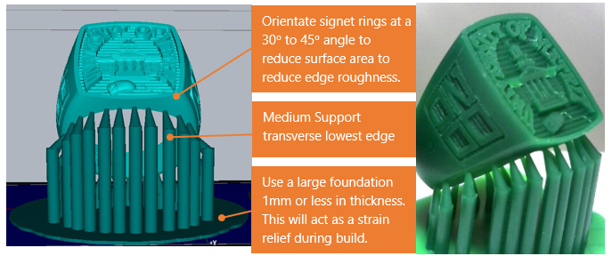
- Signet Rings – use a large diameter foundation 1mm or less in thickness. Thick foundations can cause failures.
- Resin shrinks by 1 to 3% after cure. To improve accuracy, the design should be scaled.
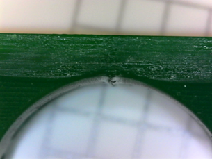
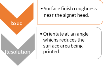
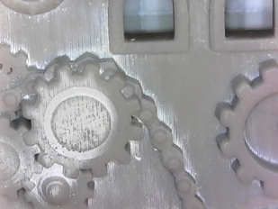
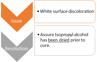
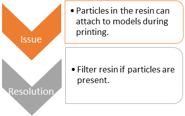
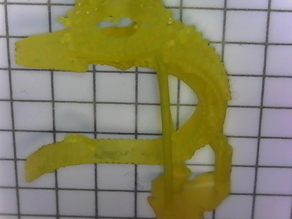
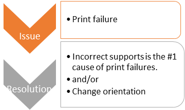
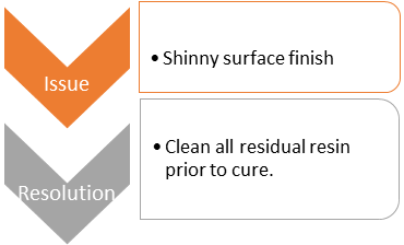
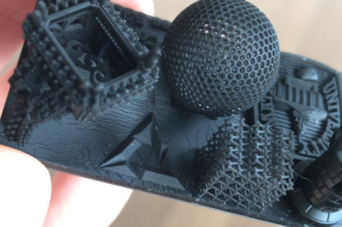
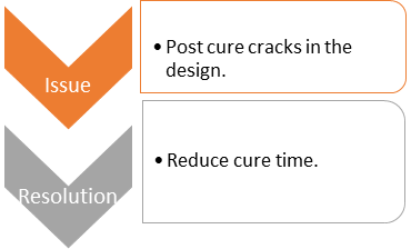
Printing Issues |
|
 |
 |
  |
 |
 |
 |
 |
 |
 |
 |
 |
 |
 |
 |
pdf (2.18 MB)
Updated by Matthew Glover 12/2/22