B9Creator Projector Tuning Process
Print Created by: Joel HrachovecB9Creator Printer Tuning Process
This document explains the recommended procedure to properly calibrate your B9Creator v1.2 3D printer to print at the highest quality output.
Things to Know
This document is for printer tuning only and it is extremely important that the user has completed the build table calibration and the projector calibration before continuing with this process. This process was completed in the factory prior to shipping. You would use this procedure when switching to a different type/color of resin than the machine is currently calibrated for or to enhance the output accuracy of the machine. To accurately measure the calibration print for this process, you will need a properly calibrated, metric measuring device, such as a caliper. (within 0.01mm of precision) This is crucial to your success. If you have not yet calibrated the build table or the projector focus or require additional assistance on this tuning process, please go to:
- Build Table Calibration: https://www.b9c.com/support/documentation/instructional-videos/build-table-calibration
- Projector Calibration: https://www.b9c.com/support/documentation/instructional-videos/projector-calibration
- How to Print Calibration Prints: https://www.b9c.com/support/documentation/instructional-videos/how-to-print-printing-your-first-calibration-prints
- Calibration Print Analysis and Printer Tuning: https://www.b9c.com/support/documentation/instructional-videos/calibration-print-analysis-and-printer-tuning
*For the printer calibration process, you will be using the B9 calibration files provided in the software downloaded onto your computer. These files are in your computer at: PC > Documents > B9Creator > Calibrations. Use the file based on the resolution the projector was calibrated to (30xy, 50xy, 70xy) and which machine you have (v1.1, v1.2).
*For this example, a 30xy calibration print will be used. If you would like to use 50xy or 70xy, please follow the projector calibration process for your selected resolution then use this document to tune the printer.
Tuning Process
1. Once the build table calibration and the projector focus calibration have been completed, before you begin this process, we strongly encourage the user to record the existing Printer Specific Settings for Balance, Fade, Machine Specific Multiplier, Normalization Slope, and X and Y Axis Calibration Multipliers. These settings are initially customized by the factory prior to shipping to ensure the machine operates within factory designated specifications. Your customized settings, with the exception of the axis multipliers, are documented on the serial number sticker to the left of your projector on the back plate for historical reference.
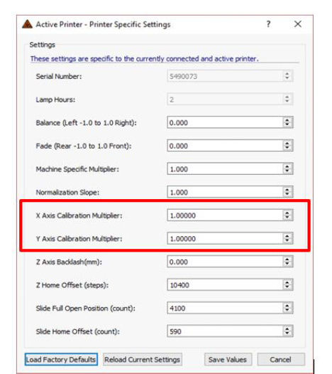
2. To view the current settings, open the B9 software. Select “Settings” then select “Printer Settings…” The Factory Default settings are shown below:
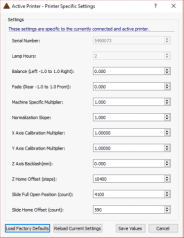
NOTE: If you are enhancing the output accuracy of your machine, start this process using the Printer Specific Settings and proceed to the next step of the process. If you are switching resin, clear the Printer Specific Settings by clicking on “Load Factory Defaults” in the lower left-hand corner. Then click on “Save Values” to update the printer settings.
3. From the main menu, click the “Print” button and then double click the desired calibration file, to begin the printing process. The file options for calibration are as shown below:
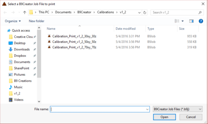 Once you have selected a calibration file to print, begin the print by clicking the ‘Create’ button on the next menu and follow the on-screen prompts to complete the software steps.
4. Once the print is finished, remove it from the build table with a thin tool such as a putty knife or scraper. Then clean the print by rinsing with warm water or isopropyl alcohol in an ultra-sonic cleaner to remove any excess liquid resin. Emerald, yellow, red, and cherry resins can be successfully cleaned with just warm water while it is recommended that DENT and black resins be cleaned with isopropyl alcohol.
5. Follow the manufacturer directions to cure the print in the B9 Model Cure.
6. To measure the calibration print, start by measuring and recording the length and width of each of the five cubes. A Calibration Measurement Sheet is located on our website here: : https://cdn2.hubspot.net/hubfs/4018395/B9creations-Dec2017-Theme/PDF/b9-calibration-measurement-sheet.pdf
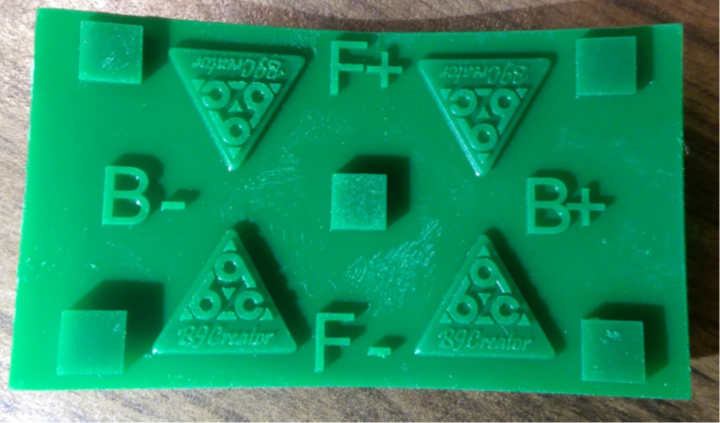
7. Figure 1 shows an example of a calibration print:
Figure 1
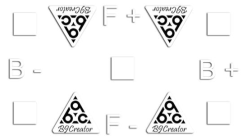
At 30xy resolution, the target dimensions for the squares on the calibration print are 5x5mm. Due to several factors affecting accuracy, the print may be slightly larger or smaller than the target dimensions. The accuracy and basic tolerance you are searching for is +/- 0.03mm. A successful 30xy print will measure between 4.97mm and 5.03mm. (At 50xy and 70xy resolution the squares are 10x10mm. The tolerances are .06mm and .1mm respectively. A successful 50xy print will measure between 9.94 mm and 10.06mm. A successful 70xy print will measure between 9.90mm and 10.10mm.)
After the initial print using the selected settings, measure the squares and record the readings on calibration measurement sheet. If the measurements are not within the recommended range Use the guidelines below to adjust each setting to obtain the most accurate results. Balance and Fade will adjust the squares printed on the outside edges. Once these are accurate, you will adjust the MSM and Slope to bring the middle square into range with the outside squares.
*Print and measure a new grid after each adjustment for the best results. This process typically requires multiple prints to successfully fine tune the machine to the optimum performance. It is recommended to adjust one factor per print cycle.
Once you have the measurements there are a few options as to what the next step is. The options consist of:
- Balance – Adjusts the left and right side. Default value is 0.0 (Use the Help/? Button on the software to understand Balance).
If the squares on one side measure larger than the squares on the other side, the balance needs to be adjusted. If the left side measures larger, adjust the balance in the positive direction. If the right side measures larger, adjust in the negative direction. Adjustments should be made in +/- 0.1 percent intervals.
-
Fade - Adjusts the top and bottom. Default value is 0.0 (Use the Help/? Button on the software to understand Fade).
If the squares on the top or bottom edge measure larger than the squares on the other edge, the fade needs to be adjusted. If the bottom measures larger, adjust the fade in the positive direction. If the top measures larger, adjust the fade in the negative direction. Adjustments should be made in +/- 0.1 percent intervals.
- Machine Specific Multiplier (MSM) – Adjusts overall exposure time. Default value is 1.0 (Use the Help/? Button on the software to understand Machine Specific Multiplier).
The goal is to have the lowest possible MSM while still obtaining a high-quality print. If the center square measures above 5.00mm, lower the MSM. If it measures below 5.00mm, raise the MSM. If the details of your print appear blown up, “puffy”, or larger than normal tolerances, the MSM needs to be decreased. Adjustments should be made in +/- 0.1 percent intervals. This needs to be adjusted before Slope.
*Projector must be calibrated as precisely as possible, MSM changes should not be used to make up for errors in projector calibration. If you find you are making significant increases to the MSM to obtain a successful print, check the projector focus calibration.
- Normalization Slope – Adjusts the amount of time the projector in-fills before the full image is exposed. Default value is 1.0 (Use the ‘Help/?’button on the software to understand Normalization Slope).
If the outside squares are measuring larger or smaller than the middle square, then the slope needs to be adjusted. If the outer squares are larger than the middle square, decrease the slope. If the outer squares are smaller than the middle square, increase the slope. Adjustments should be made in +/- 0.1 percent intervals.
Once the calibration print is within acceptable tolerances you have completed the calibration process. (If you are tuning for dimensional accuracy, please see section III. OPTIONAL: Dimensional Scaling Process.)
OPTIONAL: Dimensional Scaling Process
When tuning linear dimensional accuracy, you will need to measure the overall distance from the outside edge of one square to the outside edge of the opposite square on both the X and Y axis, to adjust for dimensional scaling. It is suggested that you leave your calibration prints on the build table for cleaning and measuring to avoid warping in the print.
X-axis/Y-axis Calibration Multiplier – Adjusts the scaling of the print in the X and Y directions. Default value is 1.0 (Use the Help/? Button to understand X-axis and Y-axis Calibration Multiplier).
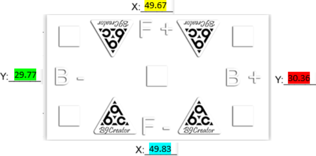
Increasing the X or Y-axis Calibration Multipliers decreases the printed length in those directions. Decreasing the X or Y-axis Calibration Multipliers increases the printed length in those directions. To adjust, first start by measuring the outside edges of the squares on the calibration print (as shown in Figure 2) then follow the equation below.
Target Measurements from edge to edge as shown below for:
• 30xy are: x-50mm y-30mm
• 50xy are: x-90mm y-50mm
• 70xy are: x-100mm y-70mm
Figure 2:
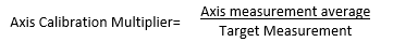
The axis multipliers are a ratio between the software’s measurements and the printed result. To calculate the ratio, take the measured value along both X-axis edges (top and
bottom in example).
Find the measurement average by adding them together and dividing by 2. Divide that value by the target measurement (referenced above example) then enter the result in the appropriate multiplier setting. Repeat this process along the Y-axis edges (left and right edges in the above example).
The equation for the Axis Calibration Multiplier looks like:
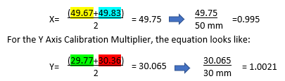
EXAMPLE:
This example will help you calculate the ratio for the X and Y Axis Calibration Multipliers. The measurements below are an example of what on a calibration print for Axis Calibration Multiplier measurements.
For the X Axis Calibration Multiplier, the equation looks like:
For the Y Axis Calibration Multiplier, the equation looks like:
The solution you calculate from each equation is the number you enter in the appropriate ‘X or Y Axis Calibration Multiplier’ field, shown below:
Repeat this adjustment until the desired accuracy is achieved.
Once the calibration print is within tolerance, you have completed the calibration process.
The picture below is an example of a good calibration print. If you have any questions or comments regarding your B9Creator please create a ticket.
pdf (715 KB) J Joel is the author of this solution article.