B9Creator Correcting Z Motor Banding
Print Created by: Joel HrachovecB9Creator Correcting Z-Motor Banding
Tools Needed:
- Hex key (i.e. Allen wrench) 7/64” (2.78mm) in diameter
- Small Philips screwdriver approximately 1/8” (3.18mm) in diameter
- Large Philips screwdriver approximately 5/16” (7.94mm) in diameter
- Carpenter speed square or perfect 90° angle marker
- Hex socket wrench size 7/64” (2.78mm)
- Flat surface to lay printer down
Procedure:
1. Unplug all cables from the machine. Remove the vat, build table, and sweeper.
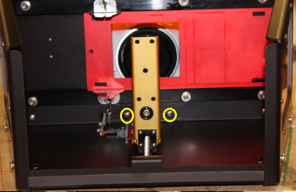
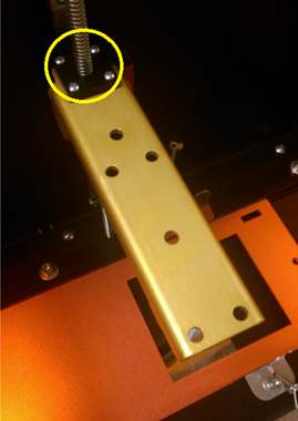
2. Remove the 4 screws from the top of the black anti-backlash nut, where it attaches to the gold arm. This will allow the gold arm to travel freely from the bottom of the z-axis slide to the black nut on the z-motor.

3. Slide the gold arm down to separate it from the black anti-backlash nut, and then slide it back to align with the bottom of the nut, as shown in the following picture.
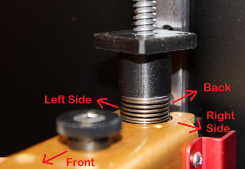
If there is any contact between the gold arm and the black anti-backlash nut, make a note of where the contact is occurring and complete step 4. If the gold arm is rubbing on the right or left side of the gold arm, proceed to step 5 after step 4. If the contact occurs at the front or back, proceed to step 8 after completing step 4.
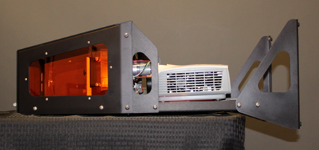
4. Lay the printer flat on its back. To allow the machine to lay flat, either set the printer at the edge of a table or counter to allow the foot supports hang off the edge or temporarily remove them.
If contact occurs along the left or right side
5. Begin by loosening the 4 black hex screws attaching the gold arm to the slide rail.
6. Adjust the gold arm slightly from side to side as needed to eliminate contact. Move the arm to the left or right until it can slide over the backlash nut without rubbing or catching on either side.
7. Tighten the 4 black hex screws. and reinsert the silver screws removed previously from the top of the gold arm assembly. If the gold arm now moves freely, you are done after completing this step. Screw back in the 4 silver screws, reattach the legs if needed, stand the machine upright, reconnect all the cables and reinstall the build table, vat, and sweeper. If the gold arm is still making contact at the front or back, continue to step 8.
If the contact occurs on the front or the back
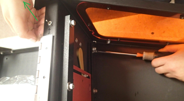
8. Remove the hatch by unscrewing the six screws attaching the hatch to the hinge. This will give you a spot for your hand to pull on the base plate in the following steps.
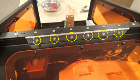
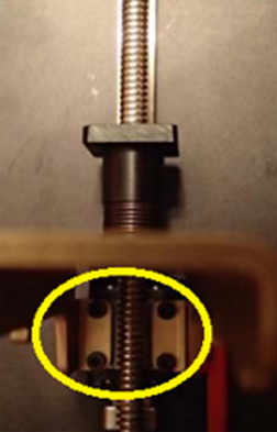
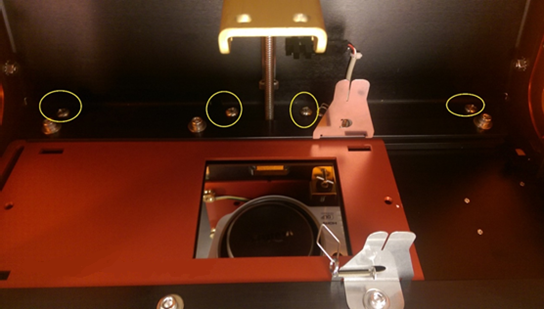
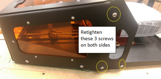
9. Loosen the screws shown below in preparation for the next steps. There is a total of ten (10) screws to be loosened. Do not completely remove any screw
Loosen these 4 screws inside the hatch
10. Place a socket wrench on the nut corresponding to one of the screws below that is closest to one side. This will help hold the nut in place when both of your hands are busy.
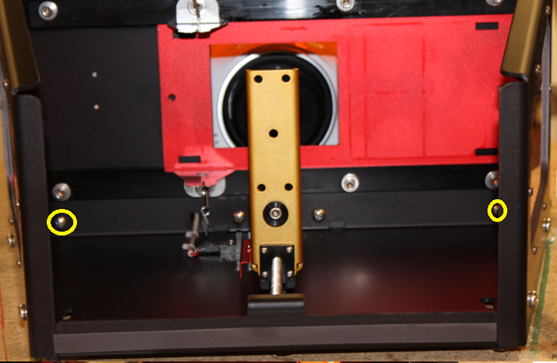
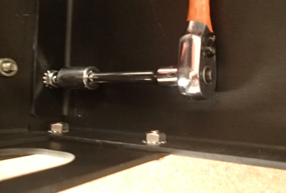
11. Pull up from underneath the x-axis base plate on the side where the socket wrench was placed. At the same time, tighten the screw on the outside closest to the corresponding side. Repeat steps 10 and 11 on both sides.
12. Tighten the center two screws. This time you will not need the socket wrench or to lift the base plate up.
13. Verify that the gold arm now slides over the black nut without friction. If it still makes contact, repeat steps 9-12. If the friction is in the back, lift the x-axis baseplate with more force. If the friction is in the front, use less force when lifting the x-axis base plate. If there is still friction after completing this process three times, create a ticket.
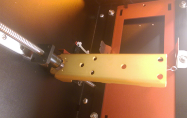
14. Place a carpenter’s square inside the hatch along the back of the printer, toward one side, as shown below. Rotate the base plate around the x-axis until there is no gap visible between the edge of the slide rail and the end of the square, as shown in the second picture below. This means the x-axis is perpendicular to the z-axis.
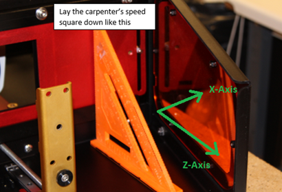
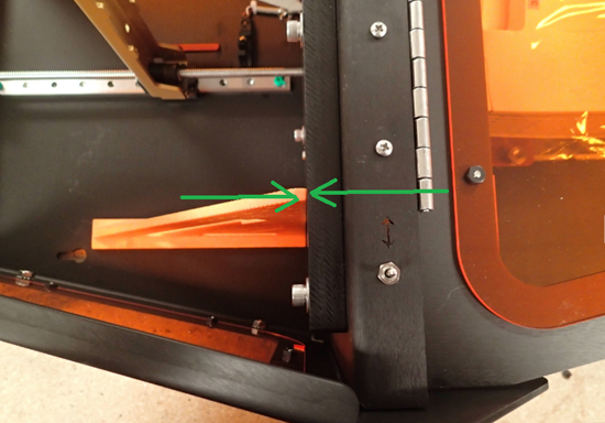
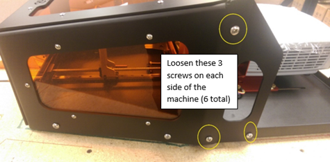
15. Re-tighten the 3 screws on each side, while holding the base plate steady and with no gap between the carpenter’s square.
17. Reattach the legs if needed, stand the machine upright, reconnect all the cables and reinstall the build table, vat, and sweeper.
18. You are now ready to print! We recommend you complete the process to calibrate the build table and fine tune the projector at this time.
pdf (712 KB) J Joel is the author of this solution article.
